Ford Mustang GT 1996-2004: How to Install Shift Light
You've been taking your souped up Ford Mustang GT to the local drag strip to race, but you keep getting your butt kicked because your rev limiter keeps stealing your acceleration? Continue reading to find out how to install a shift light to your Mustang GT.
This article applies to the Ford Mustang GT (1996-2004).
You have spent a lot of money tuning up your Ford Mustang GT: bought that racing exhaust, improved your intake, got the new ignition, and on and on. But, you are still missing that one link that will pull it all together for you at the track or wherever it is that you may be racing, which of course is not on any public street doing illegal racing. Well, maybe you should install a shift light. With some very simple tools and little bit of time, you too can install a shift light into your little Pony. This handy little gadget tells you exactly when to shift your Pony, so you don't hit the rev limiter—then zoom, nice smooth shifting all the way to the finish line.

Materials Needed
- Small slotted pry bar
- Set of screwdrivers (including star drivers)
- Set of small sockets
Step 1 – Remove door pillar and run shift light wire harness
Remove the driver's side door pillar by gently pulling on it. The pillar is only held on by clips, so it should just pop off. Feed the wire harness down through the dash. From under the dash, pull the cable down and toward the powertrain control module (PCM), which is located behind the kick panel.

Figure 1. The door pillar and harness. 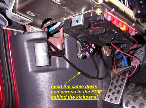
Figure 2. Under the dash.
Step 2 – Remove kick panel and door sill
Using the small pry bar, remove the push pins holding on the kick panel. Then remove the door sill, as this sits on top of the end of the kick panel. The kick panel should now come free, exposing the PCM module.

Figure 3. Kick panel. 
Figure 4. Slotted pry bar. Use to remove the push pin and the door sill. 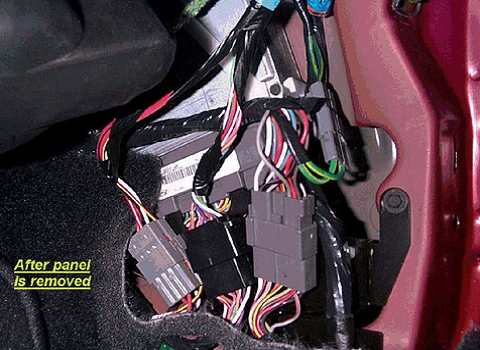
Figure 5. The kick panel removed.
Step 3 – Remove PCM module connector
Remove the two screws holding the PCM mounting bracket, as well as the green ground screw. Loosen the bolt to the PCM connector. You should now be able to access the PCM pins.
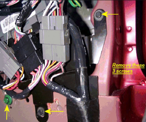
Figure 6. Remove the screws and the ground screw. 
Figure 7. Loosen the PCM pin nut. 
Figure 8. The PCM pins.
Step 4 – Remove connector pin cap and connect shift light wires
Pry the clips on the top of the connector pin module to expose the wires. Connect the green wire from the shift light to the C.O.P. wire. Then, connect the ground wire to the ground. The red wire will be connected to a fused and switched 12 volt source.
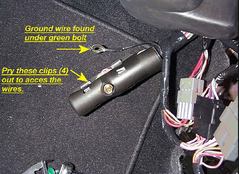
Figure 9. Connector pin cap clips. 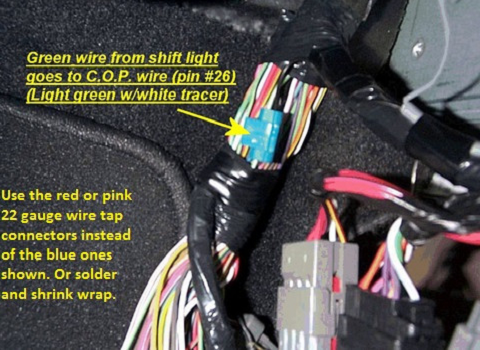
Figure 10. Connect the shift light. 
Figure 11. Ground wire. 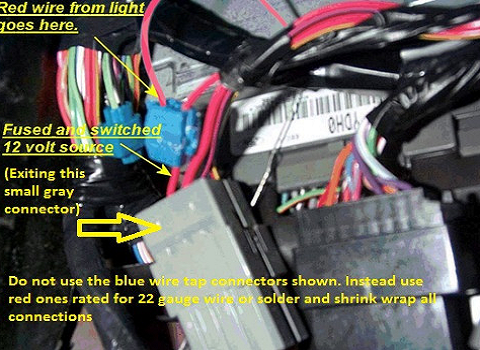
Figure 12. Power source.
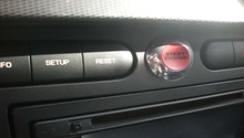
Step 5 – Mount shift light
Remove the three screws holding on the dash panel. Feed shift light from underneath and through to the dash opening, following along a gauge cluster. Replace the dash panel and attach the shift light mount to one of the screw mounting points.

Figure 13. Remove dash screws. 
Figure 14. Shift light. 
Figure 15. Shift light mounted.
Related Discussions
- Raptor Shift Light Write-up - MustangForums.com
- Want to Install Shift Light, How to Detect RPM - MustangForums.com
- Summit Adjustable Shift Light - MustangForums.com
- Cobra Shift Light - MustangForums.com